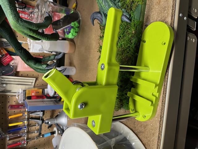
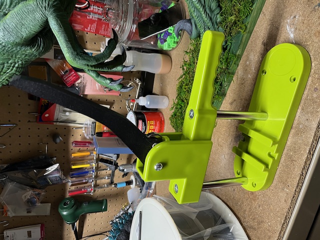
The button maker Wes uses at Bones in Jars broke, so I brought it down to the lab to see what we could do. The handle snapped, and upon inspection it was easy to see why. It's made of plastic and clearly not enough of it.

Like always, my first thought was to print a replacement, but it's a very unusual, kind-of "organic" shape and not something my OpenSCAD skills excel at. I figured I'd be stitching it back together, maybe reinforce it with a steel rod or something like that but then I had an idea.
I've been reading the Gingery books and one of the cooler applications of sand casting that he mentions is using it to produce copies of parts that are broken by assembling the pieces and pressing them into the casting sand together. The sand doesn't know the difference between a whole part or a part made of broken pieces, so once this is done, you can cast a new part as if the broken one was never broken in the first place.
I wondered if I could accomplish a similar thing in the realm of digital parts by taking a photo of the broken handle pieces and extruding the silhouette into three dimensions?
I floated this in a "maker friends" group chat to see if anyone had tried this before and of course Pete had written a blog post about it years ago. The main difference was that he suggested using a scanner (just a regular 2D scanner, not a fancy 3D one) instead of a camera, so I gave that a shot.
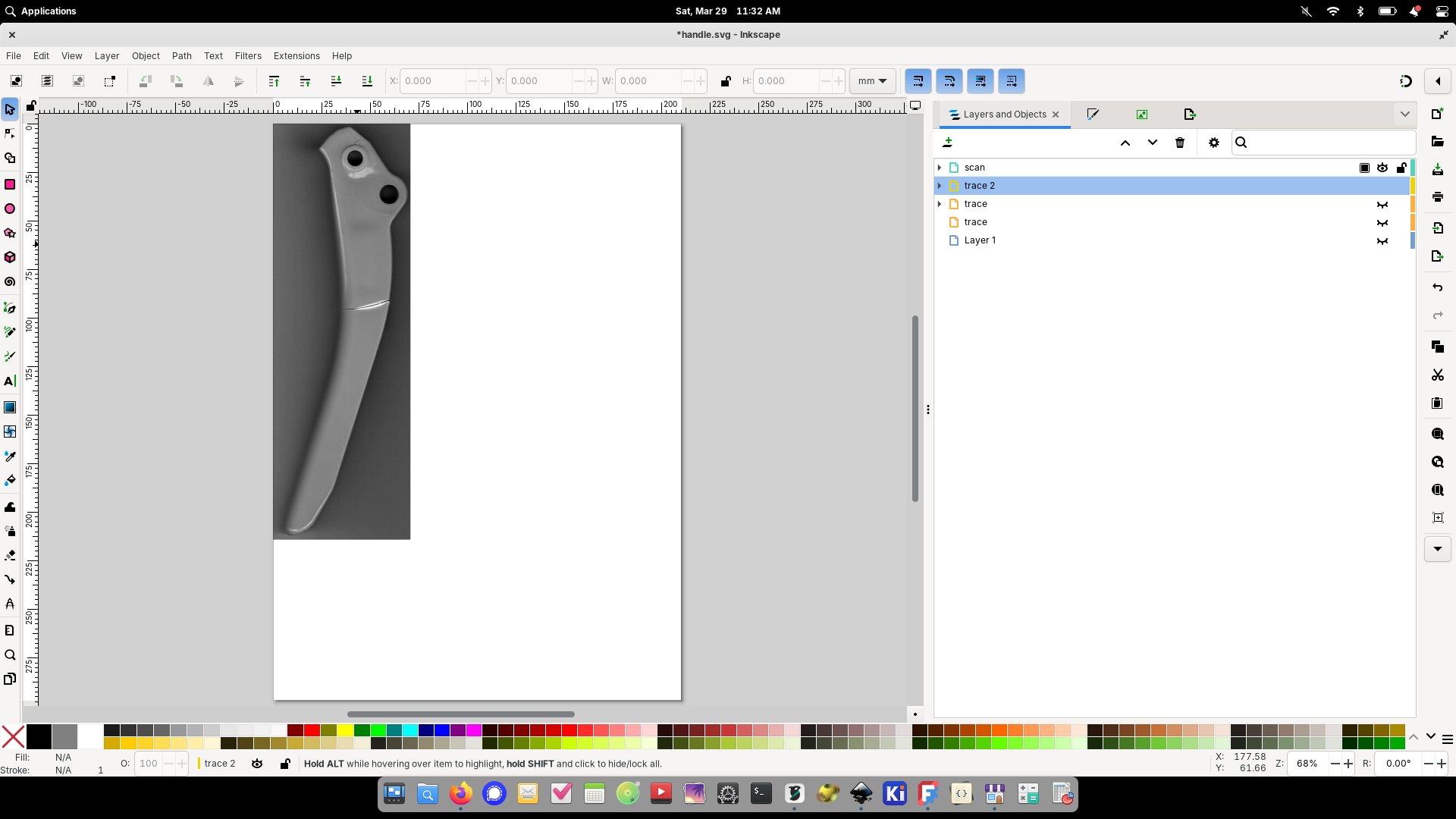
Once I got the part scanned I pulled the image into Glimpse to crop-out the stuff I didn't need and then brought it into Inkscape to convert it into a vector drawing of the profile of the part.
Tracing the cropped scan in Inkscape. The greyscale scan kinda looks like an X-ray of a broken bone...
The next step was to bring it into OpenSCAD to extrude it into a three-dimensional part, but for some reason I wasn't able to save files from OpenSCAD (I'm guessing some silly modern Linux problem) so I was kind of stuck. I've been looking for excuses to learn FreeCAD, so I decided to try that instead.
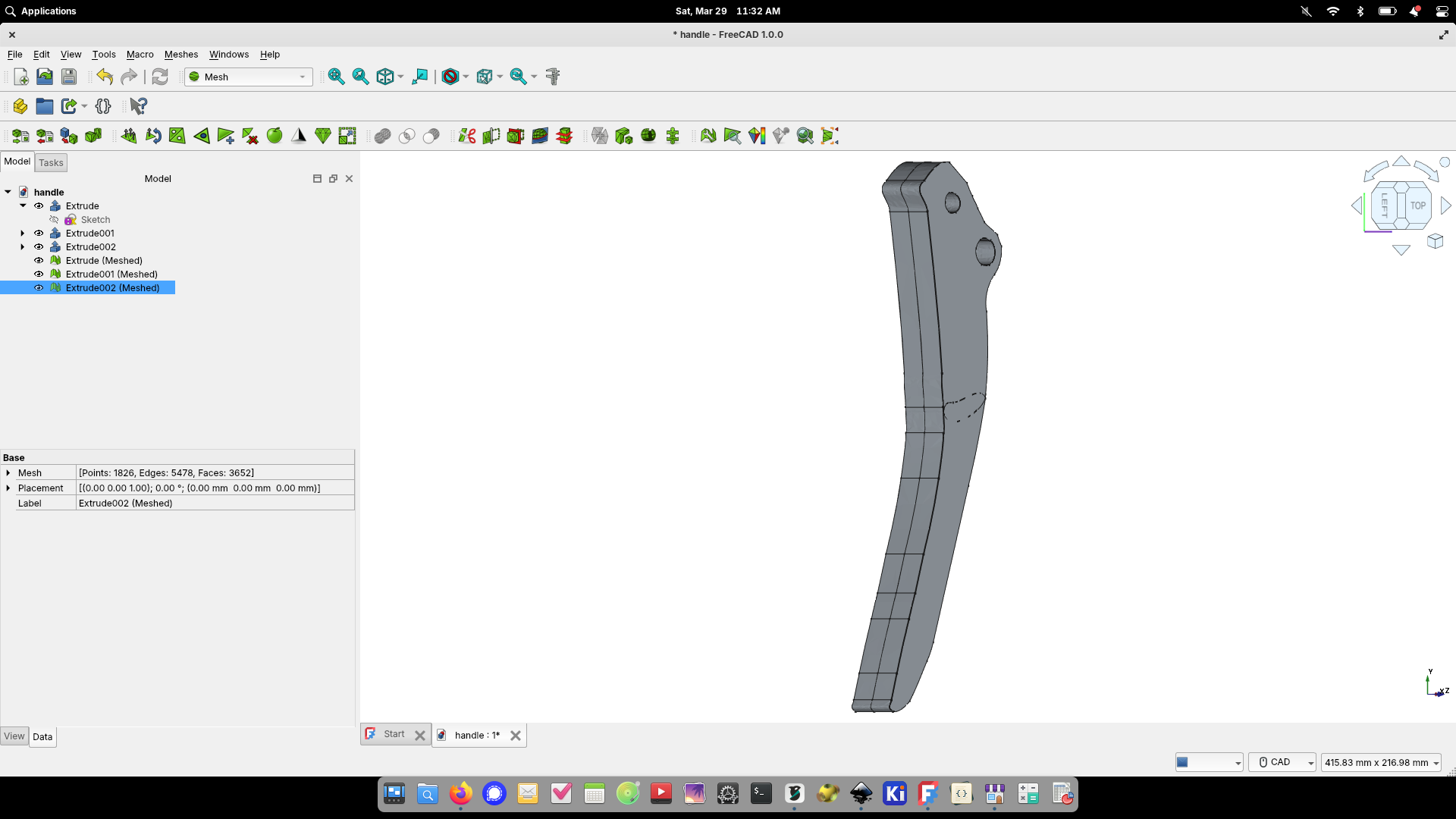
It took a lot of reading and trial-and-error, but I eventually figured-out how to extrude the 2D SVG file into three dimensions in FreeCAD.
The learning curve was steep, so it took a lot longer than it probably would have for me to do it in OpenSCAD, but eventually I figured it out, and it was cool to do something practical with FreeCAD instead of just working tutorials.
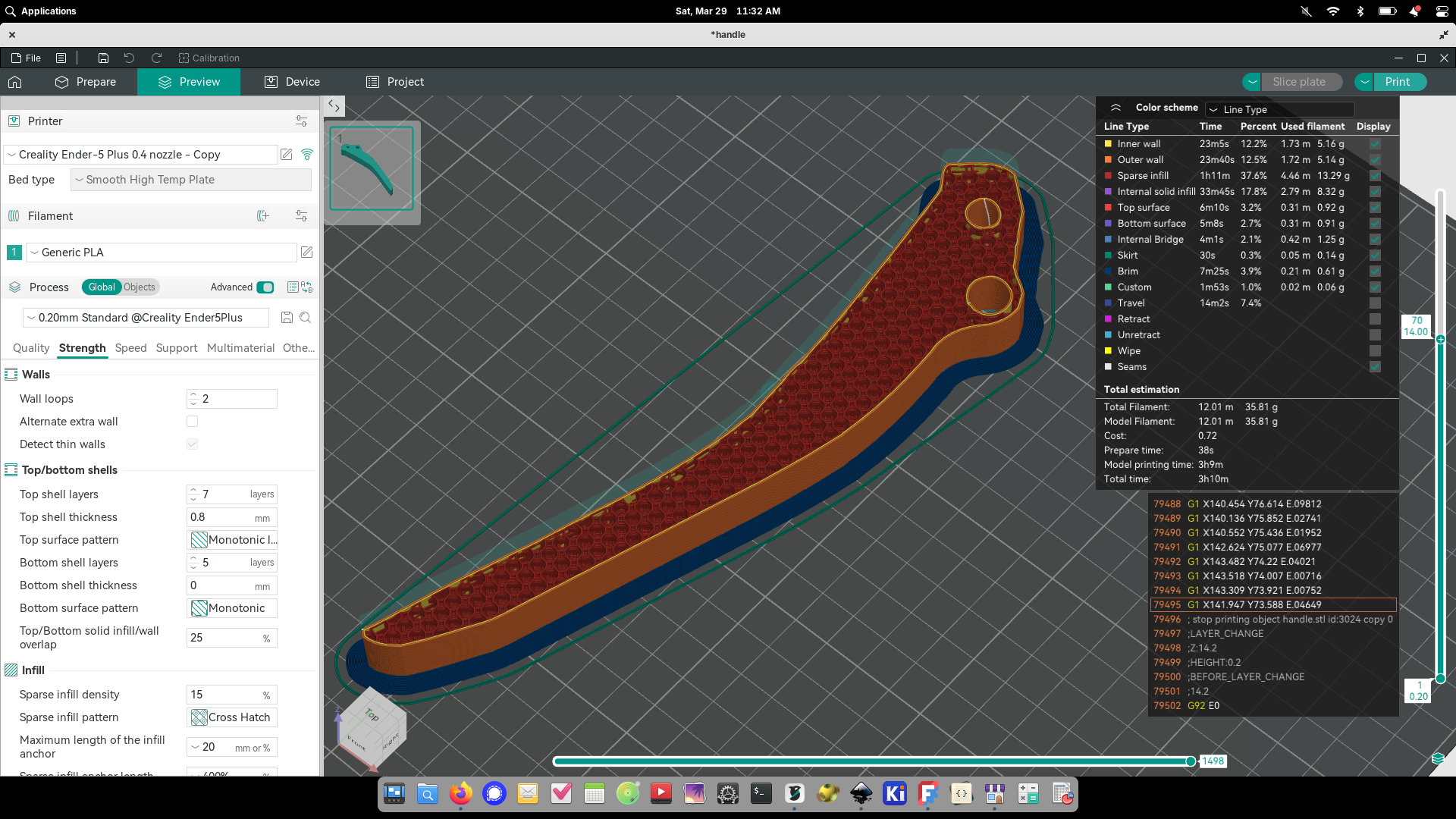
From there it was just a matter of printing it like any other part. It took two tries to get it right (needed to re-work one of the mounting holes), and I made the second print a lot stronger so that it might hold-up better than the original.
Slicing the first iteration of the new part. The second iteration was sliced with 5 wall loops and 50% infill for strength.
What completely surprised me about this process is that even though so many steps and multiple applications, the scale of the part was preserved. At no point did I have to resize/scale it and it came out of the printer a perfect match!
Side-by-side of the new printed part (left) and the original broken part.
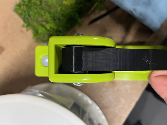
With one small change (increasing the inside diameter of the hole that holds the bearing pin), the replacement handle fit perfectly!
In addition to the new handle, I added two steel flat washers to center the handle (the original had bit of a flange in the plastic for this, but that would have made it more difficult to print, and steel is stronger anyway right?) and then gave it a good cleaning & lubrication before reassembly.
I'm happy to say that it's been put back to work and shows no signs of failure!
For reference I'm going to dump the notes I took during the process below. This is mostly just a reference so I don't forget everything by the next time I need to do this (as opposed to an actual tutorial), but if you find it useful then even better!
Make a thing from a scan
* Scan the part in a scanner
* Crop the image to the interesting part in Glimpse
* Import into Inkscape
* Path -> Trace Bitmap
* Use Brightness cutoff mode
* Use "Invert Image"
* Adjust threshold until all of the part remains
* Apply
* Click "Layers & Objects"
* Select "image1" and hide it
* Double-click the part to highlight the path
* At this point you can try Path -> Simplify to try and make things easier
* Maybe other operations can simplify it better?
* Deselect the path, then select and delete individual nodes that you don't need
* Toggle the visibility of the "image" to check for deviation
* When it looks good, delete the "image" node and save the file
* Open FreeCAD, open a new document and select the "Part" workbench
* File -> Import -> select the SVG from above, choose "SVG as geometry"
* Select all the parts and switch to "Draft" workbench
* Click "draft to sketch" button
* Select the sketch(s), switch to "Sketcher" workbench
* If there's more than on sketch, Sketch -> Merge Sketches
* Switch to the "Part" workbench
* Click the "Extrude" button
* Enter the size in the "Length -> Along:" field, click OK
* Switch to the "mesh" workbench
* Make sure the part is selected, then click Meshes -> Create Mesh From Shape
* Click OK
* Hide everything but the mesh so you can see what it's really going to look like
* Make other changes as desired
* Right-cick the mesh and select Export, ASCII STL, give it a name and click "Save"
References